Toolbar
Some of the toolbar functions are permission-based, which means that they will only be visible to a user that possesses the necessary privileges to access their functionality.

The toolbar contains the following buttons:
|
Button |
Description |
|---|---|
|
|
The Template button opens a new dialog for different layouts of the Operator Console. |
|
|
The Customize button opens a new dialog for various modifications of the Operator Console. |
|
|
The Remoting button opens a new dialog for screen layout configuration of Remote Consoles. |
|
|
This button opens the Quick Export dialog window. You can perform an export or create a cut list from cameras which are shown in the viewers. |
|
|
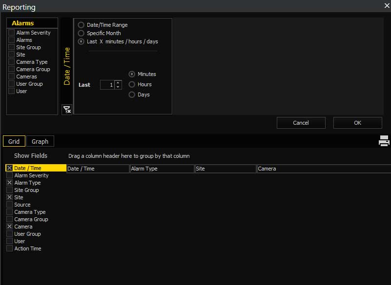
The Reporting button opens the Reporting dialog window. In this window you can generate reports about alarms based on different criteria. |
|
|
The Failover button opens the dialog that displays the states of all NVRs in the system. |
|
|
The Mute button mutes alarms. |
|
|
The Video Sound button mutes video sounds. |
|
|
The Speak button enables or disables the microphone, facilitating audio transmission to a camera equipped with a speaker. |
|
|
The Sync button turns on/off viewer synchronization mode for all/selected viewers. The first selected viewer will be the master viewer. All other viewers will get play mode and time stamp from the master viewer. |
|
|
The Select All button selects all viewers of the current screen. |
|
|
The Stretched View button turns on/off the Stretched View Mode. In stretched mode, the video frames of the camera fill all the viewer, and the viewer header is hidden. When stretched mode is off, the video frames of the camera are stretched accordingly to the camera type aspect ratio, and the viewer header is shown. |
|
|
With the Activity Areas button turned on, areas with activities are marked within the viewer. |
|
|
The OSD button opens the OSD settings dialog window where you can select which information (camera name and time, event information, viewer number) should be shown in the viewers. |
|
|
The Timeline button turns on/off the timeline. When it is off, the buttons which activate play modes are shown directly in the selected viewer. |
|
|
The Search Mode button enables you to perform a Motion Search (MOS). When the Search Mode is on, you can set up zones in the viewers where the search will be performed and get results. |
|
|
The Tabbed Lists button is used for showing/hiding the tab page lists and for changing tab page and lists items. |
|
|
The Alarms button shows/hides the alarm screen when alarms with automatic display are present. |
|
|
The Camera Check button opens the dialog that displays the result of the camera check. |


Template
In the Template Selector you can select a template or layout for a screen. The templates or layouts are created in the ManCon (for more information see Viewer Template).
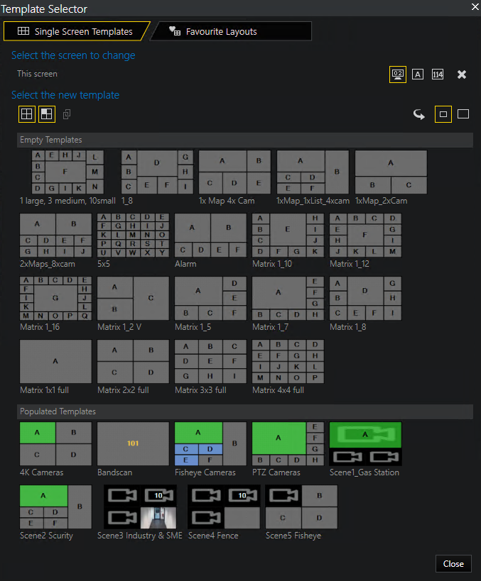
Single Screen Templates
In the Single Screen Templates tab you can select which information is displayed on your monitor or in the viewers and select a template or layout for the selected screens.
Select the screen to change:
In the Select the screen to change area you can select the screen that you want to configure by clicking on the  icon. With the following icons you can show or hide the displayed viewer information:
|
Icon |
Description |
|---|---|
|
|
With this icon you can display the global monitor number on the monitor. |
|
|
With this icon you can display the viewer ID's in the viewers. |
|
|
With this icon you can display the viewer global numbers in the viewers. |
|
|
With this icon you can clear all viewers on the selected screen. |


Select the new template:
In the Select the new template area you can select another template for the selected screen. Generally, you can select between Empty Templates (see Template Definitions), Populated Layouts (see Populated Layouts) and Linked Layouts (see Linked Layouts) which are created in the ManCon. With the following icons you can display the different templates or layouts:
|
Icon |
Description |
|---|---|
|
|
With this icon you can display empty templates. |
|
|
With this icon you can display populated layouts. |
|
|
With this icon you can display linked layouts. |
|
|
With this icon you can mirror the displayed templates. |
|
|
With this icon you can display a smaller view of the templates. |
|
|
With this icon you can display a larger view of the templates. |


Guard Tours, maps and cameras in the thumbnails of the populated layouts are marked as follows:
|
Marking |
Description |
|---|---|
|
|
Guard Tour |
|
|
Guard Tour (locked) |
|
|
Map |
|
|
Map (locked) |
|
|
Camera |
|
|
Camera (locked) |
|
|
Empty |
|
|
Empty (locked) |


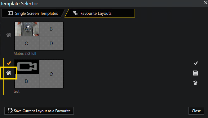
Favourite Layouts
Under the Favourite Layouts tab you can save favorite OpCon views. A favorite set as default will be used when you start up G-SIM.
If there are various favorite layouts, the orange Currently Applied checkmark indicates which layout is currently used.
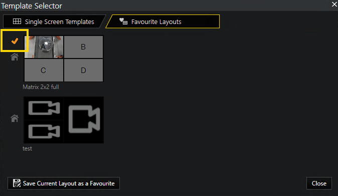
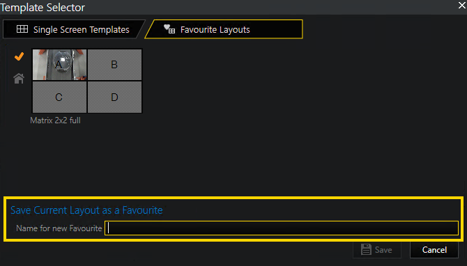
How to save the current layout as a favorite:
-
Click on the Save Current Layout as a Favourite button. The Name for new Favourite input field is displayed.
-
Enter a name and click on the Save button. The layout is now listed under the Favourite Layouts tab.
-
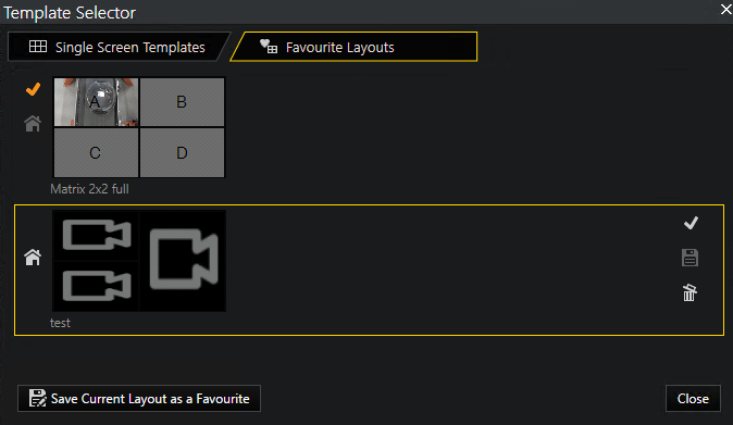
To apply the layout, select it and click on the Apply this Layout icon.
To delete a favorite layout or to save your configurations, select the layout and use the respective icon on the right.
If you want to set a favorite layout as the default layout, use the Use as default Layout icon.
Customize
In the Customize tab, you can customize general and input / device settings for the operator console. The settings are saved on a user-specific basis.
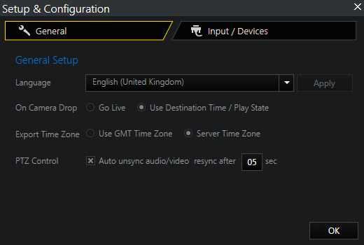
General:
Under the tab General, you can make the general settings for language and time.
|
Setting |
Description |
|---|---|
|
Language |
Select the language for the user interface of the Operator Console. Click Apply to use the selected language. |
|
On Camera Drop |
Select which time is used for playback when you open a camera in a viewer.
|
|
Export Time Zone |
Select the time zone you want to use for export. You can choose between the GMT time zone or the server time zone. |
|
PTZ Control |
Enable or disable the audio/video synchronization during PTZ control.
|
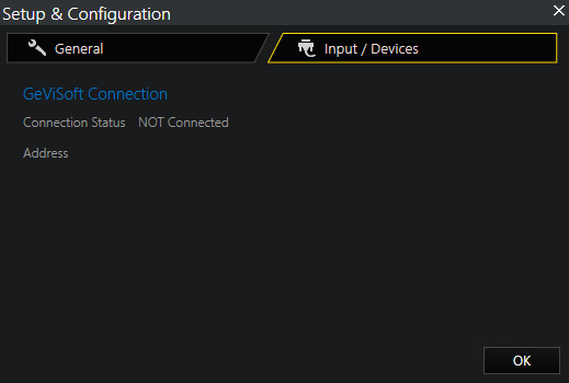
Input / Devices:
Under the Input / Devices tab, the GeViSoft connections are displayed. They are only displayed if you have installed devices such as an MBeg controller or GeViSoft.
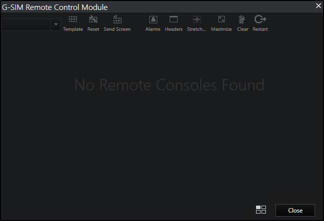
Remoting
The Remoting button allows you to configure the screen layout for any Remote Console as well as to save favorite screen setups for them. See Remote Consoles for detailed information on Remote Consoles and their remote control.
Reporting
The Reporting button opens the dialog for reporting alarms. Here, you can set user-defined filters to create alarm reports.
Failover
The Failover button opens the Failover Overview dialog.
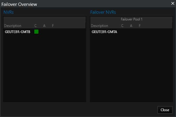
Here the states of all NVRs in the system can be displayed in a graphical view:
|
State |
Description |
|---|---|
|
C (Connected) |
Indicates whether the recorder is connected or not. |
|
A (Available) |
Indicates that the recorder is a spare and ready to handle a failover. |
|
F (Failover) |
Indicates that another recorder is in a failover state and handled by this recorder. |
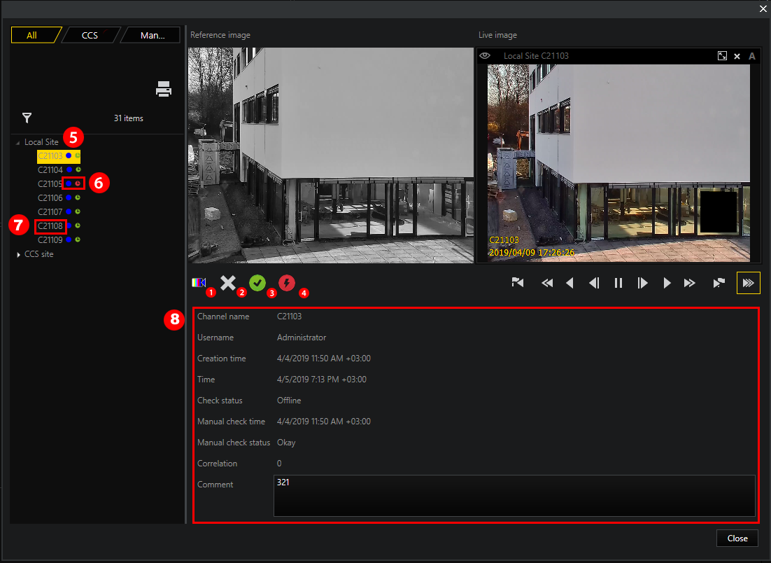
Camera Check
The Camera Check button opens the dialog that displays the result of the camera check.
|
Marking |
Description |
|---|---|
|
|
With this button you can turn an image from the livestream into a reference image. The service immediately applies it for comparison. |
|
|
With this button you can remove a reference image. |
|
|
With this button you can set the manual status to "OK" by clicking this button. |
|
|
With this button you can set the manual status to "Not OK" by clicking this button. |
|
|
Indication of the camera location. |
|
|
LEDs indicating the camera status:
|
|
|
Indication of the camera name. |
|
|
Information on the selected camera is displayed. |
Speak
The Speak button is an integral part of the 2-way audio transmission feature. It empowers the operator to transmit audio through a microphone to a camera. This is applicable to cameras that are configured with the ONVIF plugin and are equipped with either an internal or an external speaker.
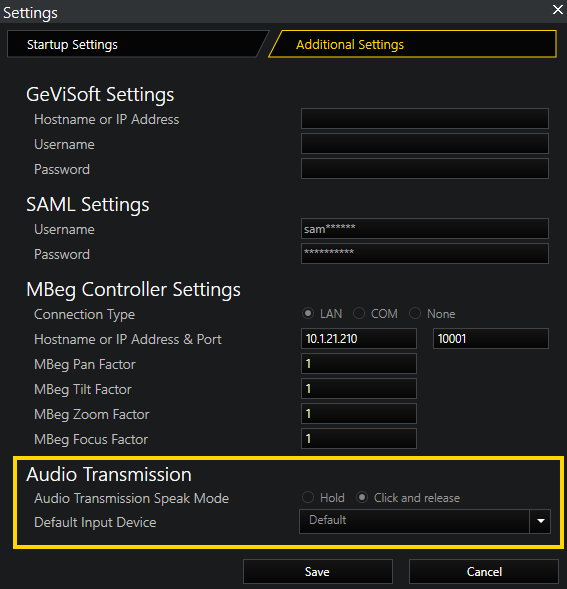
How to configure the input device:
-
Open the Settings in the OpCon log in window and navigate to Additional Settings > Audio Transmission.
-
Select the Audio Transmission Speak Mode to configure the Speak button behavior. You have two options here:
-
Hold: Voice is transmitted while button is pressed.
-
Click and release: First click activates voice transmission. Second click deactivates voice transmission.
-
-
In the Default Input Device drop-down menu, select the default microphone.
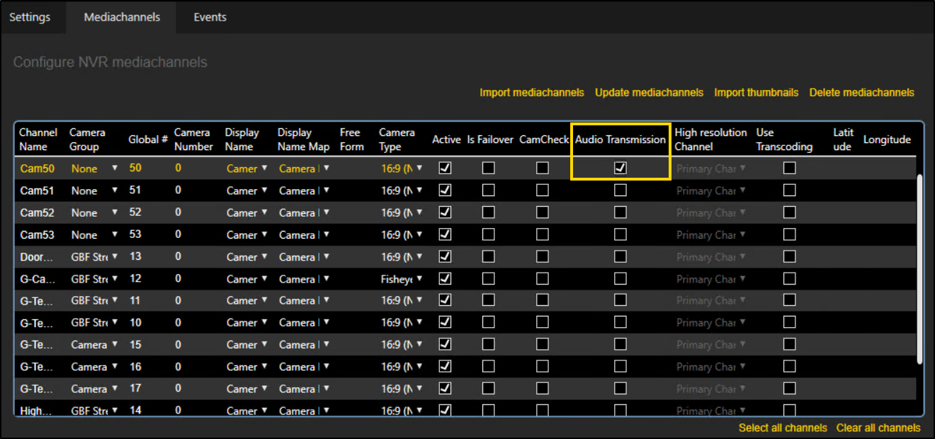
How to set up the camera for audio transmission:
In the ManCon interface, in the section NVR & Cameras > Mediasources > Recorder > Mediachannels, ensure that the camera (either possessing a speaker or connected to one) is marked as capable of Audio Transmission.
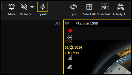
Indication of the status of the Speak button:
The Speak button is normally grayed out. It is only active if a camera capable of audio transmission is selected in a viewer. If you select such a camera and click the Speak button, the icon changes from a muted icon to an active microphone icon. Additionally, a blinking red recording symbol appears in the viewer.
It is not possible to select multiple viewers simultaneously for multicast or broadcast audio.
Motion Search (MOS)
You can detect motions with the motion search (MOS) function in live images (see MOS Live) or in the background for a determined range of time (see Background MOS).
Presettings in ManCon
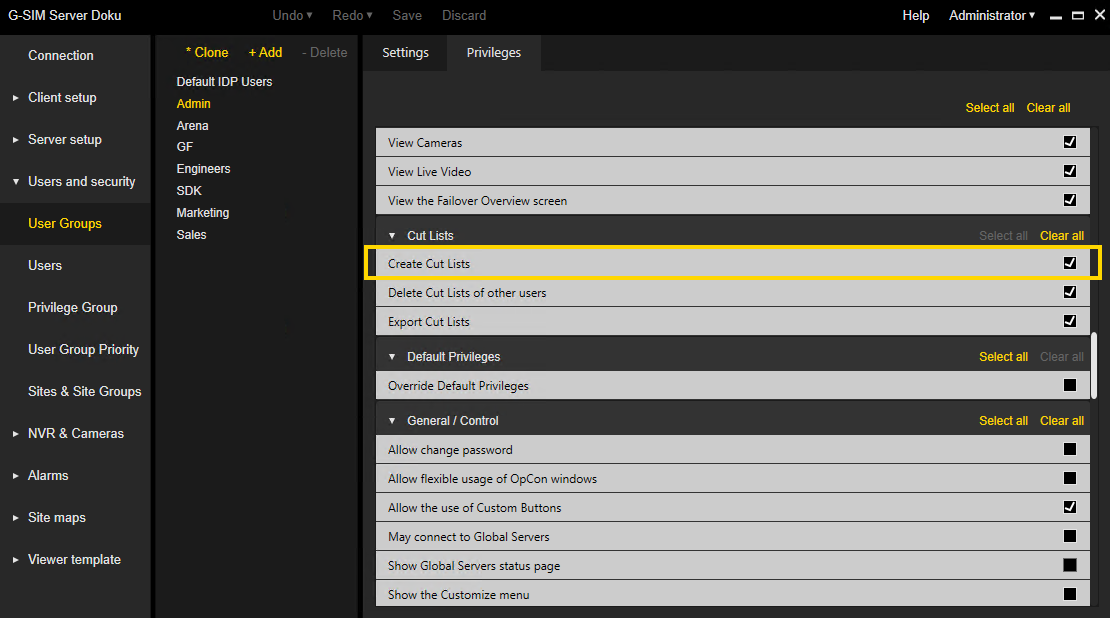
Before you can use the MOS functionality, enable the two privileges Create Cut Lists and Motion Search (MOS) in the ManCon. Note that these privileges can be enabled for User Groups and individual Users. Additionally, there are two optional MOS settings.
How to enable the necessary privileges:
-
To enable the privilege for user groups, go to Users and security > User Groups. To enable the privilege for a user, go to Users and security > Users.
-
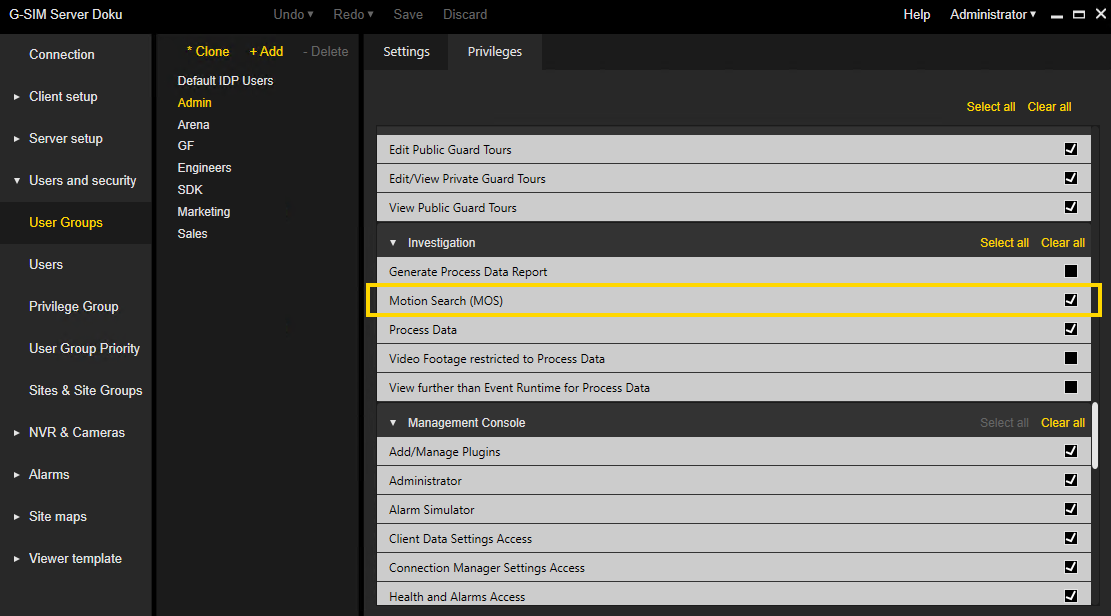
Select the user group/user for which/whom you want to enable MOS and open the Privileges tab.
-
Under Cut Lists, enable the privilege Create Cut Lists.
-
Under Investigation, enable the privilege Motion Search (MOS).
Additional Settings:
-
Color of rectangle border:
You can change the color of the rectangles which are drawn on the viewer for MOS under Client setup > Client Data > Console Settings > MOS (for more information see Client Data).
-
Default cut list item length:
You can change the default length of the cut list items by adjusting the value of the setting Default Cutlist Item Length in Seconds under Server setup > System Settings > Operator Console.
This setting applies to all cut lists in your OpCon.
MOS Live
With MOS Live, you can detect motions in live images. Define a rectangle as an area in which motions are detected. When there is a motion, the rectangle gets another color and, if enabled, there is a brief sound. Additionally, an automatic MOS cut list with the detected motions can be created. With the respective control icon you can jump back to the previous detected motion.
How to use MOS Live:
-
Select the viewer in which you want to activate the MOS Live function.
-
In the toolbar, enable the Search Mode. The
 icon appears in the viewer toolbar.
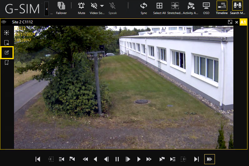
-
Click on the
icon. -
Draw a rectangle to mark the area in which motions are to be detected.
The rectangle can only be drawn from the top left to the bottom right and must be larger than 10x10 pixels.
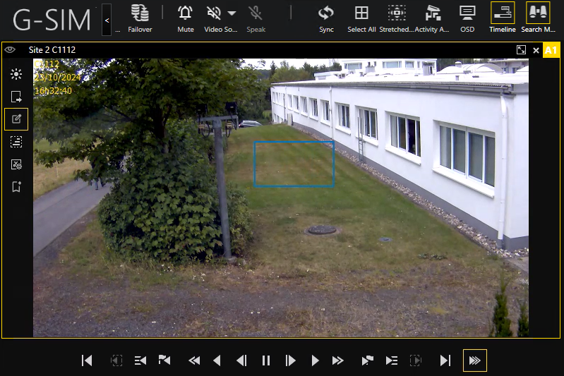
The motion detection is active. When there is a motion, the color of the rectangle changes and, if enabled, there is a brief sound.
-
If you want to disable or enable the sound (depending on the current setting), right-click into the viewer. A context menu opens where you can click either Disable Sound or Enable Sound.
-
If you want to create a cut list with the detected motions, click on the
 icon.
icon.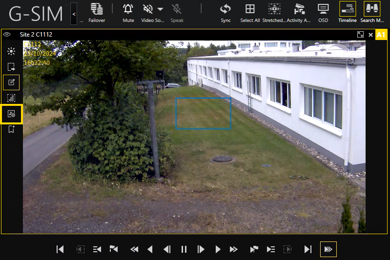
Every time a motion is detected, the respective image is added to the cut list.
If a new motion is detected and the recorded time falls into the current section of the cut list, nothing happens. If the recorded time is outside the current section time, a new section is added to the cut list. If you make any camera changes, such as zooming, pausing, etc., the current cut list is ended and the
icon is deactivated.
Background MOS
With Background MOS, you can define an area and a time range in which motions are detected. Additionally, you can set the motion sensitivity. The Background MOS runs in the background and automatically creates a cut list with the detected motions.
IMPORTANT: Before you can use Background MOS, you must activate the G-Tect Activity Detection (AD) service on the G-Core server in G-Set > Image analyzers (see G-Core documentation).
How to use Background MOS:
-
Select the viewer in which you want to activate the Background MOS function.
-
In the toolbar, enable the Search Mode. The
icon appears in the viewer toolbar.
-
Click on the
icon. The  icon appears in the viewer toolbar.
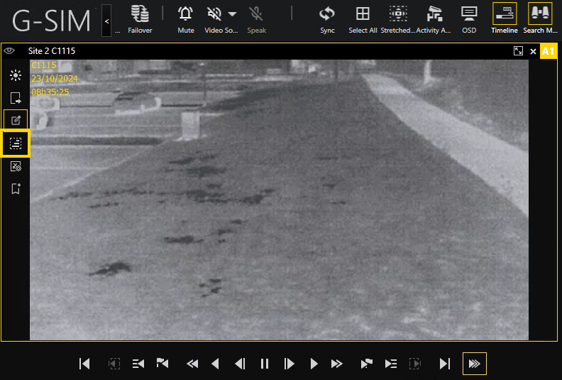
-
Draw a rectangle to mark the area in which motions are to be detected.
The rectangle can only be drawn from the top left to the bottom right and must be larger than 10x10 pixels.
-
Click on the
icon. The Background MOS menu opens.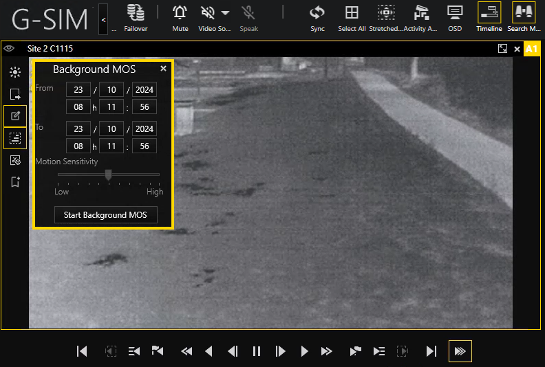
-
Select a start and end date and time of the Background MOS and set the Motion Sensitivity.
-
Click on the Start Background MOS button. A cut list is created to which images with detected motions are added automatically while the set range of time.
If there are no results for the selected search, the dialog window There are no search results to show with the selected configuration or the G-Tect AD was not activated on G-Core side opens.